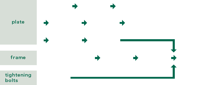
- Plate material is moved one by one to the next process.

- The manufacturing date and lot number are printed on the plate.

- Oil is applied to the plates to improve smooth sliding when pressing.

- The corrugated patterns on the heat transfer area and the shapes of the gasket lines, etc. are press molded.

- Allow light to pass through in order to check the plates for cracks. PT inspection is used, depending on the format.

- Unnecessary parts around outer periphery of the plate and slit holes in the gasket are trimmed.

- Oil is cleaned off the plates.

- The gaskets are manually attached to the plates one by one.

- Frame material that has been fused by gas is machined to process the nozzle parts and tightening bolt parts.

- Slag, spatter, and processing oil that adhered during machining are cleaned off.

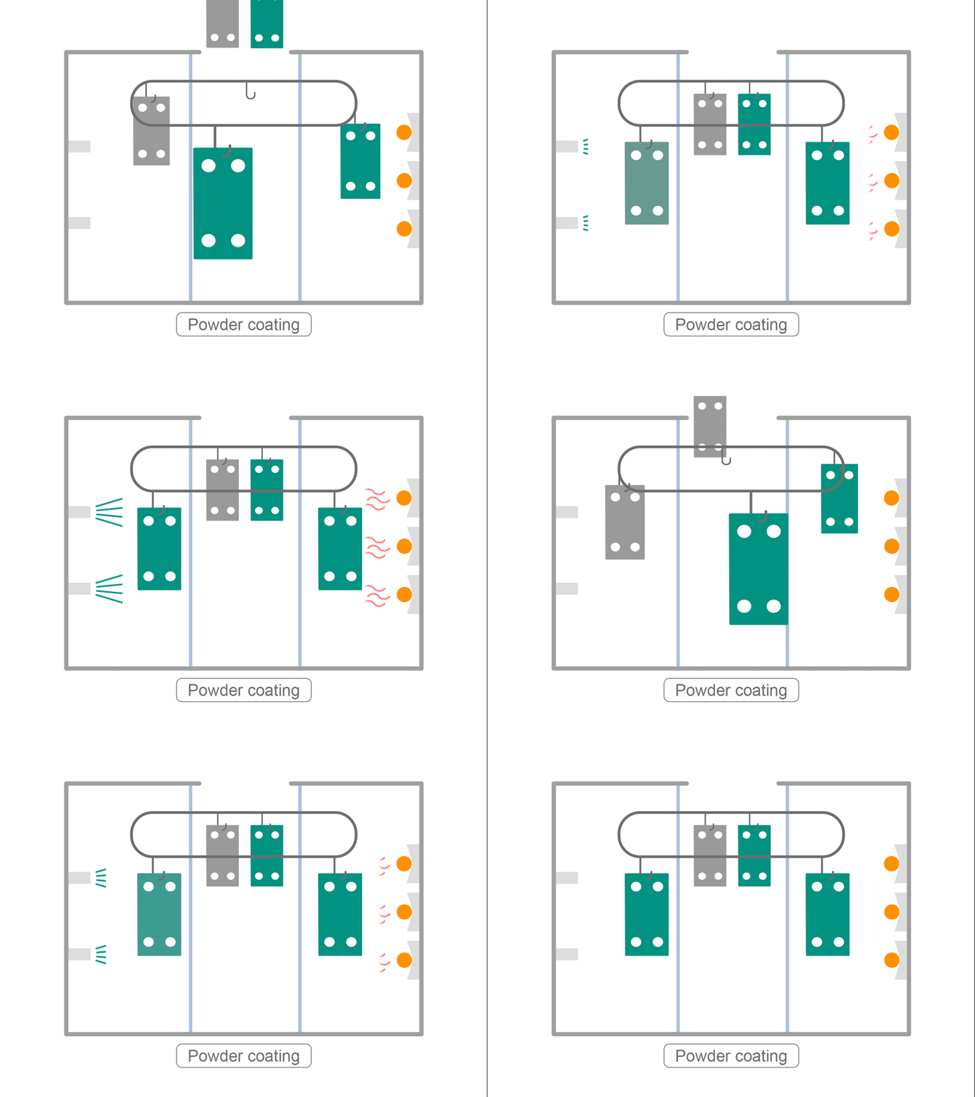
- The frame is coated by baking. Coating is applied manually, according to the size of the frame, coating color, and coating specifications.

- Frame parts are assembled, and the plates are assembled with gaskets. Tightened to the specified dimensions with the tightening bolts and nuts, inspections such as a pressure resistance test is performed. Packed and shipped.

- The cylindrical bolt material is inserted into the rolling device, threads are made on the bolts, and they are cut to required length. This might not apply, depending on the material and screw dimensions

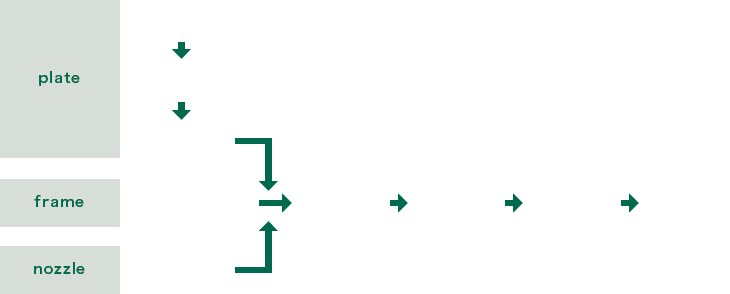
- Plate material is moved one by one to the next process.

- The plates are oiled to improve smooth sliding when pressing.

- The corrugated patterns on the heat transfer area and the shape of the outer periphery are press molded. Unnecessary parts, such as the nozzles on the plates, are trimmed.

- Oil is cleaned off.

- The outer shape and nozzle mounting holes are pressed.

- The frame, plates, and nozzles are assembled.

- The material is machined to make the nozzles.
- Insert
- The assembled product is placed in the vacuum furnace.
- Exhaust
- Since it is necessary to remove the oxidation film of stainless steel for brazing, the furnace is made into a vacuum.
- Heating
- The temperature inside the furnace is raised to approximately 1100°C to melt the brazing material.
- Cooling
- Next, the furnace interior is cooled to solidify the brazing material and the plates are brazed together.

- A submersion test is performed to check for external leakage. This might not apply for some models.

- After the inside of the heat exchanger is dried, the product is packed and shipped.
Features of PHE/BHE
PHE
- Excellent maintainability
-
The device can be disassembled simply by removing the tightening bolts and nuts, and the heat transfer plates can be removed one at a time.
After they are removed, the heat transfer plates can be washed and visually inspected.
After cleaning, assembly is as simple as disassembly.If you think this maintenance is too difficult to perform by yourself:

- Structure that prevents two liquids from mixing
-
If the fluid leaks due to deterioration of the gasket from long-term use, the leak occurs between the plate gaskets that seal the two fluids, and is discharged to the outside of the heat exchanger from the discharge section.
- Changes in performance
- You can disassemble the heat exchanger and increase or decrease the number of plates, or change the plate arrangement to change the heat transfer area and performance.
BHE
- High pressure/heat resistance
- Since the contact areas between the heat transfer plates are brazed with nickel or copper, they can withstand high pressure and temperature.
- Compact
- Lighter and more compact than PHE, because it has fewer components.
Summary of the Features of PHE and BHE
| PHE | BHE | |
|---|---|---|
| 0.1 to 7300[m3/h] | Adaptive flow rate | 0.1 to 70[m3/h] |
| 20A to 600A | Adaptive diameter | 10A to 65A |
| Up to 4.0[MPa] / Up to 180 [°C] | Adaptive pressure/ heat resistance |
Up to 4.5[MPa] / Up to 200[°C] |
| Good Can be disassembled within the installation space. |
Maintainability | Poor |
| Good | Flexible design / mass productivity |
Good |
| Good Increase or decrease the number of plates to change the specifications. |
Change capacity | Poor |
| Good | Space saving | Very good |
| Good Double seal structure DW plate |
Structure that prevents two liquids from mixing |
Moderate Countermeasure parts (DW) available. |
| Good In addition to stainless steel and titanium, nickel alloy and special stainless steel can be used. |
Material lineup (plates) | Moderate Compatible materials Stainless steel |


