TECHNOLOGYAbout Ball Valves
The valve disc, which controls fluid flow, of a ball valve is shaped like a ball.
Valves are used to stop/allow the flow of water, air, gas, powder, and other substances inside piping, and also to control the flow rate, making them useful for a wide variety of applications in our world.
Valve operation concepts can be generally divided into the following four types according to the shape of the valve element that controls the fluid flow: Pushing, rotating, sliding, and squeezing types.
Ball valves correspond to the concept of “rotating”, and are therefore used in flowing (on) and closing (off) applications for fluid flow. Additionally, the “full-bore” structure, in which the valve port and piping bore are the same, provides a valve with extremely low fluid resistance and little pressure loss. The ability to turn on/off by 90° rotation of the valve element provides excellent operability and short operating time.
Construction of Ball Valve
Ball valves generally have a structure in which the valve disc, the “ball”, is held between two seat rings referred to as “ball seats”. As mentioned above, the “stem” connected with the ball is rotated 90° to turn the valve on or off.
Ball valves consist of either a floating or a trunnion structure.
The floating structure consists of the ball being held by two ball seats so that the fluid pressure presses the ball against the ball seats. This is a general-purpose valve is commonly used due to the small number of parts and inexpensive cost.
The trunnion structure maintains the ball at a right angle to the fluid so that the springs equipped to the backside of the ball seats press them against the ball to form a seal with no reliance on fluid pressure. This structure prevents low-pressure leakage and applies a smaller load on the ball seats, even in piping to which high pressure is applied, in comparison with the floating structure, making it suitable for large-size valves.
Ball Valve by temperature
HISAKA WORKS offers a product lineup featuring ball valves for a wide range of valve applications according to fluid temperature, properties, and pressure. The following table indicates the use ranges by temperature of 2-way valves. Please note that the model may change depending on the fluid.
Valve features
| Concept | Basic Design | Strong Point | Weak Point | |
|---|---|---|---|---|
| 1 | Rotating |
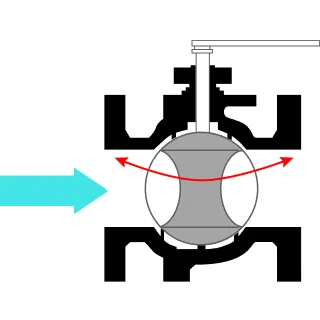 Ball valveA ball with a hole through it that opens and closes with a 90° rotation.
|
Resistance of flow: quite small Operation time: Short(by quarter turn operation) |
Flow control: un-suitable |
Butterfly valveA disc shaped like a plate that opens and closes with a 90° rotation around the central axis.
|
Face to Face Dimension: Small Flow control: Suitable Operation time: Short(by quarter turn operation) |
Resistance of flow: Big(Stem) Limited operation range by material of seal |
||
| 2 | Pushing |
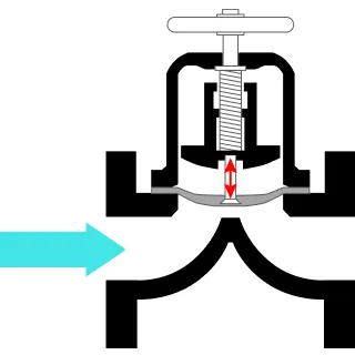
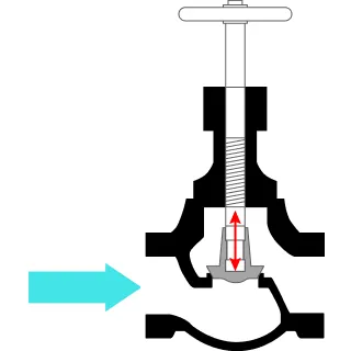 Globe valveA plug (valve body) is pushed up and down to adjust the flow rate.
|
Shut off performance: High Flow control: Suitable |
Face to Face Dimension: Large Resistance of flow: High Operation Torque: Big |
| 3 | Sliding |
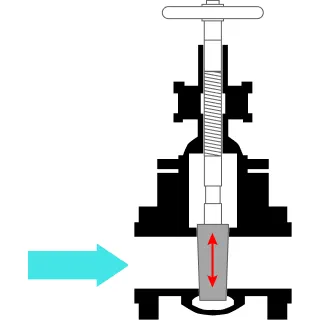 Gate valveA wedge-shaped gate is slid up and down to open and close the flow path.
|
Shut off performance: High Resistance of Fluid: Small |
Operation time: Long Flow control: un-suitable |
| 4 | Squeezing |
 Diaphragm valveAn elastic diaphragm is pressed down to squeeze and close the flow path.
|
Cleaning Performance: High(Glandless design) Suitable for Flow control Flow control: Suitable |
Limited operation range by material of diaphragm |
Supply Record
Food


Chemical


Steel


Environment

